Separate presence and pulse signals
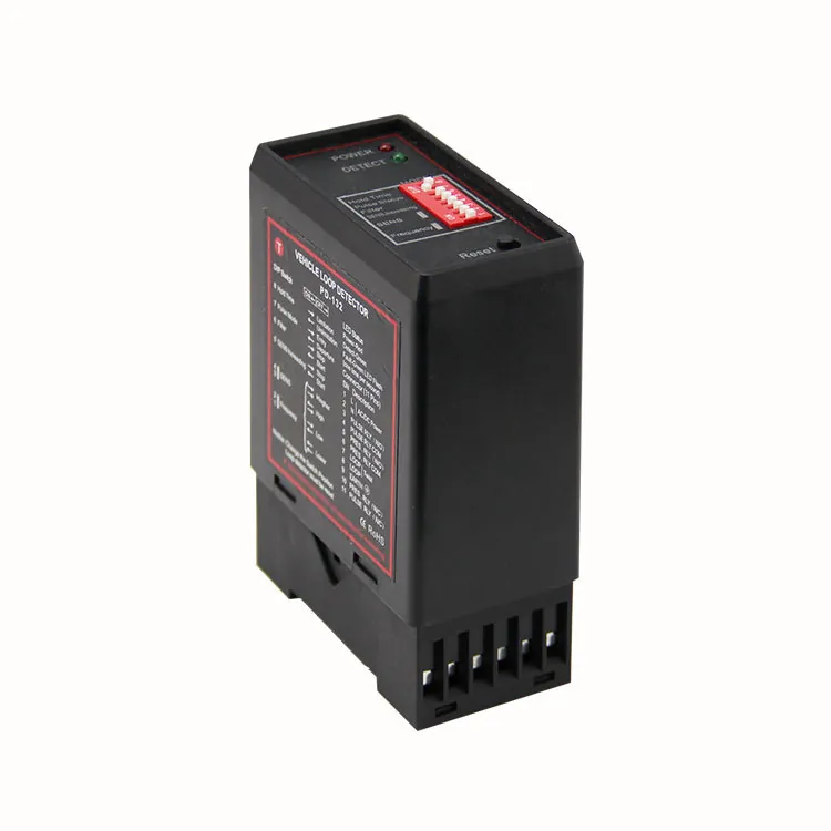
The SXK-PD182 reads one inductive loop and provides separate relay outputs for vehicle presence and pulse events. It has eight sensitivity steps and four selectable frequency levels.
Vehicle Loop Detector
The SXK-PD182 reads one inductive loop and provides separate relay outputs for vehicle presence and pulse events. It has eight sensitivity steps and four selectable frequency levels.
Barrier installers and system integrators selecting vehicle-detection inputs.
The SXK-PD182 reads one inductive loop and provides separate relay outputs for vehicle presence and pulse events. It has eight sensitivity steps and four selectable frequency levels.
Choose the presence or pulse behavior to suit the gate logic. Send the controller model and the loop layout when you request this detector.
The detector provides presence and pulse relay outputs from one inductive loop. Match each output to the function expected by the gate controller.
Eight sensitivity steps and four frequency levels support site adjustment. Recheck the response after the road loop is installed.
Detection and output behaviour must be commissioned with the selected controller and lane. A component rating is not approval of a complete safety system.
Functional sequence for configuration planning. Use the approved project drawing for physical wiring and installation.
Send these details with your enquiry so we can review the equipment and configuration.
Details for equipment review and installation planning.
Technical reference: datasheet p. 2.
Review the supplied connection drawings. Select a drawing to enlarge the labels and terminals.
Match the equipment to the site, the users and the access workflow.
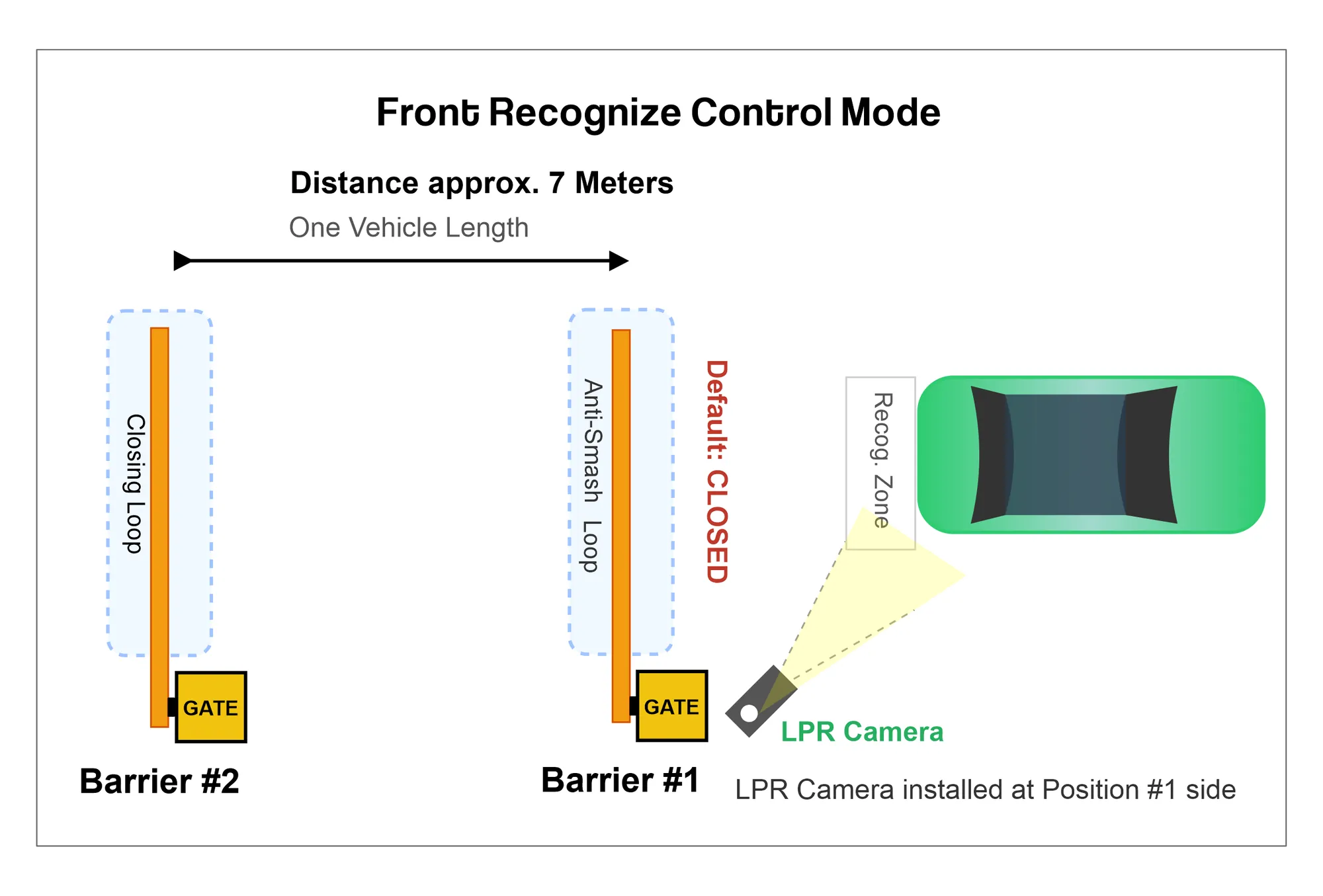
Show the detector location against the boom and stopping position. Confirm the controller input and expected presence or pulse behaviour.
Vehicle detection application illustration; detector type and placement follow the lane design.Identify the controller, supply and installed detection arrangement. Match the replacement device and retest the lane.
Project planning exampleDocument the intended sequence and detection zones. Verify outputs with the actual controller during commissioning.
Project planning exampleProduct documents for your technical review.
Product functions, specifications and configuration scope.
Questions about selection, integration and installation.
The SXK-PD182 reads one inductive loop and provides separate relay outputs for vehicle presence and pulse events. It has eight sensitivity steps and four selectable frequency levels.
Confirm the input circuit and required presence or pulse signal. Supply and output behaviour must match the exact ordered version.
Position, configuration and the site layout affect the result. For loop detectors, the installed loop and nearby devices also need review.
Test the selected detection area and output with the actual vehicles and controller. Verify the complete opening and closing sequence before handover.
Choose the presence or pulse behavior to suit the gate logic. Send the controller model and the loop layout when you request this detector.
We provide remote video technical guidance, installation videos, wiring diagrams and installation instructions. For large projects, an engineer can provide on-site technical guidance.
Send the model, quantity and installation requirements. Include your layout or controller details where relevant.
Replies within 2 hours during Beijing business hours.