From the bay to the sign
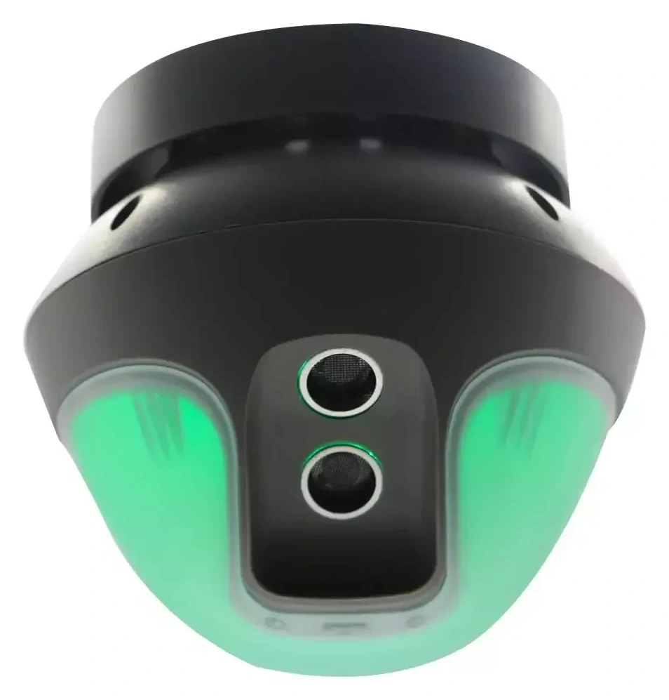
One ultrasonic sensor monitors each marked space and shows its status on an LED. Zone and central controllers collect the readings for directional signs, entrance displays and a live parking map.
Ultrasonic Parking Guidance System
One ultrasonic sensor monitors each marked space and shows its status on an LED. Zone and central controllers collect the readings for directional signs, entrance displays and a live parking map.
Parking installers and system integrators planning bay detection, controllers and vacancy displays.
One ultrasonic sensor monitors each marked space and shows its status on an LED. Zone and central controllers collect the readings for directional signs, entrance displays and a live parking map.
Send the number of bays, floor plans and proposed sign locations. We use those details to review controller groups and the equipment needed for each zone.
The car park photo shows a directional sign across the aisle and bay indicators above the spaces. Use these two types of display to guide drivers to an aisle and then to an available bay.
An ultrasonic sensor checks each monitored space and shows its status on an LED. Map each sensor to the correct bay before reviewing floor and zone counts.
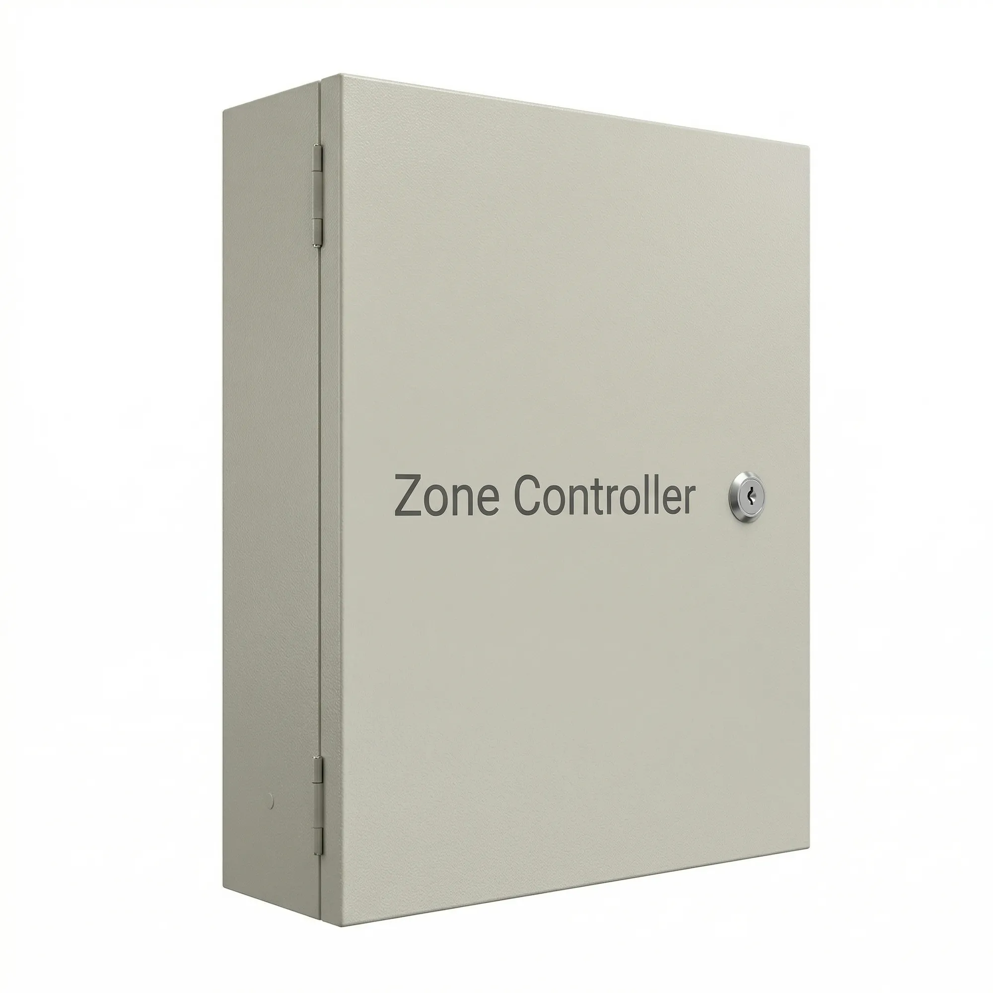
Zone and central controllers collect the readings for indoor and entrance displays. Assign each arrow and count to the route that drivers can actually take.
Controller quantities depend on the field layout and approved network structure. Include ceiling conditions, sign positions and cable routes in the floor plan.
Shared system documentation covers several models. The values on this page refer to the named device; network distances depend on compliant cabling and the approved topology.
Functional sequence for configuration planning. Use the approved project drawing for physical wiring and installation.
Supplied system topology reference. Confirm actual device counts, branches and power loading for the ordered configuration.
Send these details with your enquiry so we can review the equipment and configuration.
Details for equipment review and installation planning.
Technical reference: datasheet p. 3.
Match the equipment to the site, the users and the access workflow.
Mark the bays, mounting height and obstructions on the plan. Verify occupied and empty conditions after addressing the sensors.
Application illustrationDefine the floors, zones and cable routes before selecting controller groups. Match signs to the approved network structure.
Application illustrationPlace signs before driver decision points. Associate each arrow or displayed count with the correct zone.
Application illustrationProduct documents for your technical review.
Product functions, specifications and configuration scope.
Questions about selection, integration and installation.
One ultrasonic sensor monitors each marked space and shows its status on an LED. Zone and central controllers collect the readings for directional signs, entrance displays and a live parking map.
Quantities depend on bay count, field devices, cable routes and controller topology. Send the floor plan and proposed sign positions for review.
Review the downstream device counts, cabling and controller structure before expansion. The optional node layer is selected for the approved layout.
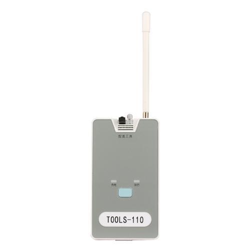
Assign device addresses, map sensors to bays and signs to zones. Verify occupied and vacant conditions, displayed counts and communication recovery.
Send the number of bays, floor plans and proposed sign locations. We use those details to review controller groups and the equipment needed for each zone.
We provide remote video technical guidance, installation videos, wiring diagrams and installation instructions. For large projects, an engineer can provide on-site technical guidance.
Send the model, quantity and installation requirements. Include your layout or controller details where relevant.
Replies within 2 hours during Beijing business hours.